An optical isolator is a device that transmits the linearly polarized
light in one direction, and stops the most of light (with any polarization)
in reverse direction. It consists of a Faraday rotator, two polarizers,
quartz rotator and a body to house the parts. The Faraday rotator, in
turn, consists of magneto-optically active optical material placed inside
the permanent magnet (Nd-Fe-B). Magneto-optical rod is cut from Magneto-Optical
Glass(MOS-10), polished to flatness l /10 and parallelism better than
1 arc minute. It is anti-reflection coated with residual reflection
less than 0.2% (each side) in the range 700-900 nm.
Quartz rotator is a crystal quartz plate with optical axis oriented
along the direction of the optical beam. The thickness of the plate
is 4,1 mm . The plate turns the polarization of the radiation at 45°
by wavelength l =800 nm. It also has anti-reflection coating with residual
reflection less than 0.2% (each side) in the range 700-900 nm. Polarizers
are air-spaced Glan prism made of natural calcite and air-spaced Roshon
prism made of natural calcite and quartz glass. Entrance and exit faces
of polarizers are anti-reflection coated with residual reflection less
than 0.3% in the range 700-900 nm.
Operation of an optical broadband Isolator
Laser light, polarized or not, enters the input polarizer P 1 and
is linearly polarized, say in the horizontal plane (0 ° ). Linearly
polarized light enters the Faraday rotator rod, the plane of polarization
rotates as the light propagates along the axis of the rod. The Faraday
rotator has to be tuned to rotate the plane of polarization by 45 °
. The light then passes through the quartz rotator and the net rotation
is 0 ° . The output polarizer P 2 is oriented at 0 ° . So, the
most of light intensity emerges from the output of the Isolator. Any
backward light re-enters the isolator through the output polarizer and
becomes polarized at 0 ° . It then passes through the QC (quartz
compensator) and Faraday rotator, where QC rotates polarization by 45
° in one direction, while the Faraday element produces 45 °
in same direction, the summary rotation becomes 90 ° and the backward
radiation is stopped by the input polarizer. Thus, the laser is isolated
from beam reflections that may occur in the application part of the
optical set. Moreover, the wavelength dependence of Faraday rotation
for backward beam is substantially compensated by that of rotation in
QC.
Optical Isolator is factory aligned at central wavelength
800nm. For this wavelength the Isolator exhibits the widest band of
operation. To re-aline the Isolator, please, use this wavelength.
Wavelength tuning
Verdet constant of the MOS rod is wavelength dependent. Thus, the
tuning of the Isolator for the definite wavelength is required. Wavelength
tuning is achieved by rotating a threaded housing which contains the
MOS rod, thereby moving the rod into or out of the magnet, more or less
of the rod is exposed to the magnetic field, thus controlling the amount
of rotation. The complete procedure of adjustment of the Isolator is
described below.
Adjustment of an optical broadband Isolator
The Isolator can be adjusted for any input light polarization. The
output light polarization is rotated 90 ° in respect to input. Adjustment
of the Isolator can be made in free steps with the help of a light beam
at working wavelength and light intensity indicator (e.g. photo-diode
+ meter).
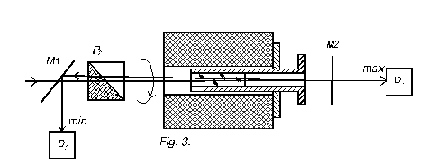
1. Adjustment of MOS rod (wavelength tuning):

M 1 – beam splitter mirror; M 2 – back-reflecting
beam mirror (reflection ~90%); D 1 , D 2 – photo-detectors.
1.1 Turn the isolator 180° so that the polarizer P 2 is the input
polarizer. Loosen the screws 4 (fig. 1) and by rotating adjust the polarizer
to maximum signal at photo-detector D 1 . Fix the screws 4 (fig. 1).
1.2. Put a beam splitter M 1 before the polarizer P 2 to direct a back-reflected
beam using mirror M 2 aside.
1.3. Free the screw-nut 2 (fig. 2) and tune the crystal holder to minimal
intensity of light reflected by a beam splitter at photo-detector D
2. Fix the screw-nut 2 (fig. 2).
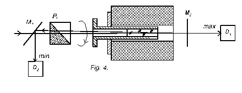
2. Adjustment of input polarizer P 1 :

• Turn the isolator 180° so that the polarizer P 1
is the input polarizer. Assemble the scheme as shown in fig. 4.
• Loosen the screws 4 (fig. 1) and by rotating adjust the
polarizer to maximum signal at photo-detector D 1 .
• Fix the screws 4 (fig. 1).
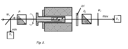
3. Adjustment of output polarizer P 2 :

3.1. Put the quartz plate into the P 2 polarizer holder and fix it
with screw 6, fig. 1.
3.2 Assemble the scheme as shown in fig. 5.
3.3. Install the output polarizer and tune it to minimal intensity of
light reflected by a beam splitter at photo-detector D 2 and to maximum
intensity at photo- detector D 1 .
3.4. Fix the output polarizer by the screws 4 (fig.1).
Remarks:
-
If polarization plane of your installation does not coincide
with isolator polarization plane (for example the isolator is adjusted
for horizontally polarized light, but your installation radiation
is vertically polarized), then you can loosen stop screw of isolator-5
(fig. 1.) and turn the isolator inside the frame until it does coincide.
-
The arrow on the frame of the isolator shows the direction of
input radiation.
-
This modification of isolator provides a side output of radiation
from input polarizer. Use protective covers to avoid eye
damage .
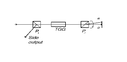
-
Avoid ingress of extraordinary ray from Roshon prism to your
photo-detectors in process of adjustment (fig. 6). When optical
isolator is aligned extraordinary ray is absent.
